A snapshot of some of the design considerations and decision points we face as we look to transition our product to market.
by Nick Lynch, Senior Hardware Engineer
As Exyn transitions out of the lab and into the real world, we’ve had to address how to deploy our industry-leading ExynAI autonomy software on to a physical product that would operate successfully in challenging industrial environments. Throughout our development, we’ve had considerable success leveraging off-the-shelf hardware to demonstrate autonomous flight. However to optimize the product for environments such as underground mines, we’ve customized the design to more closely match product requirements.
Over the past several months, we made significant strides to deliver a product design that is reliable, manufacturable, and scalable to meet our customers’ needs. This process has necessitated a top to bottom review of hardware design. Here’s a brief look inside some of the challenges and considerations that went into this exercise.
One of the key challenges within the drone market is the balance of limitations in size, weight, and power (SWAP) with the functional requirements of the system. Drones are typically designed with a specific payload and flight time (duration) in mind -- ie. how big does it need to be to carry a certain weight for a given period of time. The platform configuration -- including frame size, motors, propellers, and batteries -- are all selected to best match the payload and desired flight time. In short, the payload is the weight outside of its own platform and may include any additional sensors or cameras.
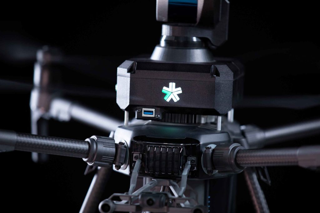
Exyn’s payload -- commonly referred to internally as our “Flight Guide” -- consists of our CPU, Interface PCBs, sensors, gimbal motor and cables to tie each subsystem together. Therefore as we are developing the production design, we are looking to minimize our size and weight to maximize operational flight time. Furthermore, optimizing around size and weight unlocks the ability to integrate with smaller drone platforms, potentially opening up new applications and customers.

Common questions we ask ourselves are: what type of interfaces are needed? Answers typically depend on the ultimate target audience for the product. Often internally as engineers, more is better -- additional USB ports to connect peripherals such as a mouse and keyboard, HDMI port for displays, ethernet for a network connection -- are great for developing and debugging yet are superfluous for the ultimate customer. In transitioning from an engineering prototype to a product release, the more we can pare back these features to match the ultimate customers’ needs, the better.
As we build confidence in the overall system throughout testing there is less need to directly interface and debug onboard. Additionally, we have designed components and subassembly level tests so that system elements such as the LiDAR gimbal assembly can be tested and verified independently as we build out the system. Naturally, the result is a reduction in the weight of the system which allows us to reduce the size of the housing and shrink the size of our bill of materials. Not to mention that such ports also act as ingress points for dust and moisture. Less of an issue in a lab setting but critically important for an operational environment that is often dirty, dusty, humid and wet.
Such changes also translate to performance improvements. Savings of just 100 grams may result in an additional minute of flight time. For the customer, this translates to additional data collected. For example, underground mining survey teams often have a limited time window in which they are operating underground. Additional flight time results in more data collected, increased efficiency, and cost savings for the mine operator, all further demonstrating the value of the Exyn system.
A natural step that follows design optimization is improvements in manufacturability. In our early stages, Exyn’s systems were individually assembled, calibrated, and tested on-site at our facility in South Philadelphia. The advantage was the ability to rapidly adapt the assembly process to design changes and quickly respond and resolve hardware issues. The disadvantage has been variability between each assembly, making quality assurance a challenge while increasing the burden on field engineers to maintain and service the systems during operation.
In the transition toward production, we are streamlining the design and formalizing the models, drawings, and documentation which comprise the Technical Data Package (TDP). A robust TDP allows us to work with contract manufacturers to fabricate and assemble the systems, ensuring quality and uniformity across production.

This process starts with the review of the Bill of Materials (BOM), which is the complete record of the parts, assemblies, subassemblies, and documents needed to manufacture the system. By some metrics, the number and diversity of components within the BOM represent the complexity of the assembly. The more complex the assembly, the longer it takes to assemble, the higher potential for quality issues, and the greater the difficulty to maintain. As a reference, a prototype system consists of over 120 individual components. There are 20 unique cable assemblies, most with different connector suppliers and requiring hand assembly. The design has more than 50 lines for assembly hardware -- screw, nuts, standoffs, etc. -- each of which has a manual installation step. Taking these numbers into consideration, our redesign for production needed to address the overall complexity of the assembly to achieve significant improvements in manufacturability.
To reduce the complexity of the system, we combined and integrated individual, often off-the-shelf, components into custom subassemblies. Where we originally had separate circuit boards for power distribution, ethernet, inertial sensors, and motor control, we were able to combine on a single interface board. With respect to cables, we adopted a standard connector series, which allows us to take advantage of pre-assembled cables. For the housing, we designed a custom enclosure that incorporates all of the mounting features within a two-part assembly. That enclosure also includes pre-assembled threaded inserts to simplify assembly. Overall, we were able to achieve more than 50% reduction in the BOM part count. As a result, we have been able to cut assembly time by nearly 75%. Correspondingly we have improved the documentation of the TDP and have begun engagement with contract manufacturing facilities to build out our systems.
Beyond product design and manufacturability, it has been important to consider the look and feel of the system to stand out in a competitive marketplace. Exyn’s system is ultimately designed to be platform independent – given the rapidly evolving drone market, we can’t be strictly coupled to a particular platform. Therefore, if a platform has the appropriate size and payload capacity, our only requirements are a serial data interface to communicate low-level commands to the flight controller and sufficient power to operate the payload. However, within those constraints, it is important to incorporate visual and aesthetic design elements that simultaneously project a fully integrated system while highlighting and promoting the Exyn branded hardware.

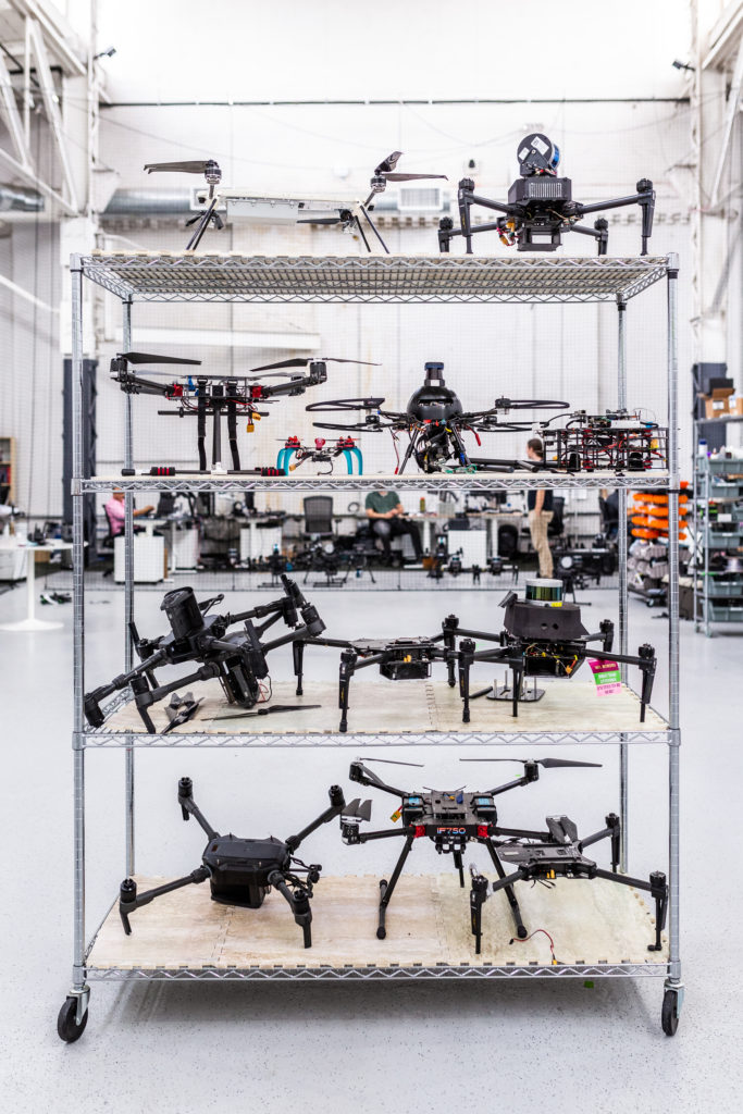
Our current system is based around the DJI M210 as the primary drone platform. In designing the new housing for the Flight Guide, we mirrored some of the angular features from the main body of the DJI M210 body to provide a consistent design language between the platform and payload. Similar features were incorporated into our initial prototypes and have been carried forward into the latest designs, maintaining a connection to some of our earliest hardware. The flight guide also features a similar matte black surface finish to match the DJI base.
To give the flight guide a unique Exyn branding, we incorporated an LED illuminated Exyn logo. Each of the 5 LEDs that backlight the logo are individually addressable within the software to create animated effects as well as provide feedback such as boot up, sensor activity, low battery, and more. A secondary trio of LED indicators are visible in flight to help the operator monitor mission status and platform health. The use of LED indicators for both status and branding is advantageous in our typical dark or low-lit underground operating environment.

This is a small snapshot of some of the considerations and decision points we face as we look to transition our product to market. As hardware engineers at Exyn we are continually striving to improve upon our designs to maximize value for our customers and provide the best possible platform to showcase the groundbreaking ExynAI software.